Introduction:
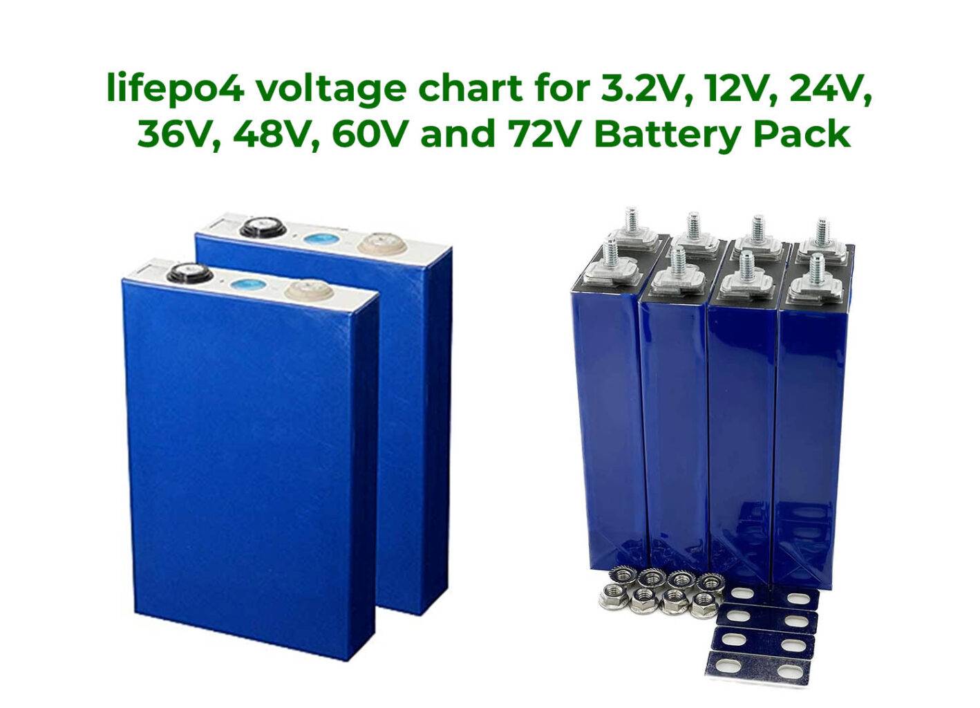
Lithium Iron Phosphate, commonly known as LiFePO4 or LFP, is a type of rechargeable battery that belongs to the lithium-ion battery family. It has high energy density, long cycle life, and inherent safety characteristics compared to other lithium-ion chemistries. Here we will discuss lifepo4 voltage chart for 3.2V, 12V, 24V, 36V, 48V, 60V, 72V and more.
How LiFePO4 Battery is Made:
LiFePO4 batteries are made using a specific cathode material, which is the LiFePO4 compound. Here’s a general overview of how LiFePO4 batteries are creating:
- Cathode Material Preparation: The cathode material, LiFePO4, which is by mixing lithium carbonate (Li2CO3), iron phosphate (FePO4), and other additives. This mixture needs to heat at a high temperature to create a stable compound of LiFePO4.
- Electrode Preparation: The cathode material, along with conductive additives and a binder, is mixed to form a slurry. This slurry then coats onto a current collector, usually made of aluminum foil.
- Anode Preparation: The anode side of the battery typically uses graphite or other carbon-based materials. Similar to the cathode, the anode material is need to mix with a binder and coated onto a current collector made of copper foil.
- Separator and Electrolyte: A separator, often made of a porous polymer, is need to place between the cathode and anode to prevent short circuits. The battery is then filled with an electrolyte solution that facilitates the movement of lithium ions between the electrodes during charging and discharging.
- Cell Assembly: The cathode, anode, separator, and electrolyte are need to assemble into a cell. The layers are stacked together, and the cell is sealed in a suitable casing, often made of metal or plastic. This is to prevent leakage and to protect the cell from external influences.
- Formation: The assembled cells go through an initial charging and discharging process, known as formation. This helps to stabilize the cell’s performance and capacity.
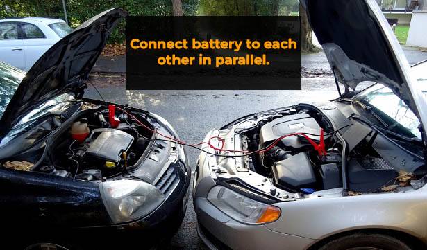
- Battery Pack: To create larger battery systems, individual cells need to connect in series or parallel configurations, depending on the desired voltage and capacity. Battery management systems (BMS) need to use. It monitor and manage the individual cells’ voltage, temperature, and current, ensuring safe and efficient operation of the battery pack.
LiFePO4 Battery Voltage Chart:
A voltage chart for lithium iron phosphate (LiFePO4) batteries typically shows the relationship between the battery’s state of charge (SOC) and its voltage. LiFePO4 batteries have a relatively flat voltage curve. This means their voltage changes only slightly across a wide range of charge levels. This voltage stability is one of the advantages of LiFePO4 batteries compared to other lithium-ion chemistries.

The distinctive properties of LiFePO4 chemistry, make it a popular choice for various applications. A LiFePO4 battery pack is made by connecting multiple individual LiFePO4 cells in a specific arrangement to achieve the desired voltage, capacity, and performance characteristics.
3.2V (1 Cell) LiFePO4 Battery Voltage Chart:
| State of Charge (%) | Voltage (V) |
|---|---|
| Discharged (<10%) | ~2.5 – 2.8 |
| 10% | ~3.12 |
| 20% | ~3.15 |
| 30% | ~3.18 |
| 40% | ~3.22 |
| 50% | ~3.27 |
| 60% | ~3.32 |
| 70% | ~3.38 |
| 80% | ~3.45 |
| 90% | ~3.55 |
| 100% | ~3.65 – 3.7 |
12V LiFePO4 Battery Voltage Chart:
To make a 12V LiFePO4 battery it’s need to connect multiple LiFePO4 cells in series. This type connection helps to reach the desired voltage level. Each cell has a voltage of 3.2 volts. Here’s a general voltage chart for a 12V LiFePO4 battery consisting of four cells connected in series:
| State of Charge (SoC) | Voltage per Cell | Total Voltage |
|---|---|---|
| 0% | ~2.50 V | ~10.00 V |
| 10% | ~2.80 V | ~11.20 V |
| 20% | ~2.95 V | ~11.80 V |
| 30% | ~3.05 V | ~12.20 V |
| 40% | ~3.15 V | ~12.60 V |
| 50% | ~3.25 V | ~13.00 V |
| 60% | ~3.35 V | ~13.40 V |
| 70% | ~3.45 V | ~13.80 V |
| 80% | ~3.55 V | ~14.20 V |
| 90% | ~3.65 V | ~14.60 V |
| 100% | ~3.70 V | ~14.80 V |
24V LiFePO4 Battery Voltage Chart:
24V LiFePO4 battery can achieved by connecting 8 cells of 3.2V in series.
| SOC (%) | Voltage per Cell (V) | Total Voltage (V) |
|---|---|---|
| 0% | ~3.00 | ~24.00 |
| 10% | ~3.10 | ~24.80 |
| 20% | ~3.15 | ~25.20 |
| 30% | ~3.20 | ~25.60 |
| 40% | ~3.25 | ~26.00 |
| 50% | ~3.30 | ~26.40 |
| 60% | ~3.35 | ~26.80 |
| 70% | ~3.40 | ~27.20 |
| 80% | ~3.45 | ~27.60 |
| 90% | ~3.50 | ~28.00 |
| 100% | ~3.60 | ~28.80 |
36V LiFePO4 Battery Voltage Chart:
To create a 36V LiFePO4 battery pack its need to connect 12 cells of 3.2V in series.
| State of Charge (%) | Voltage per Cell (V) | Total Voltage (V) |
|---|---|---|
| 0% | ~2.0 | ~24.0 |
| 10% | ~3.0 | ~36.0 |
| 20% | ~3.2 | ~38.4 |
| 30% | ~3.3 | ~39.6 |
| 40% | ~3.35 | ~40.2 |
| 50% | ~3.4 | ~40.8 |
| 60% | ~3.45 | ~41.4 |
| 70% | ~3.5 | ~42.0 |
| 80% | ~3.55 | ~42.6 |
| 90% | ~3.6 | ~43.2 |
| 100% | ~3.65 | ~43.8 |
48V LiFePO4 Battery Voltage Chart:
Please note that actual voltage values may vary based on the specific manufacturer, model, and temperature conditions. Here’s a general outline of what the voltage chart might look like:
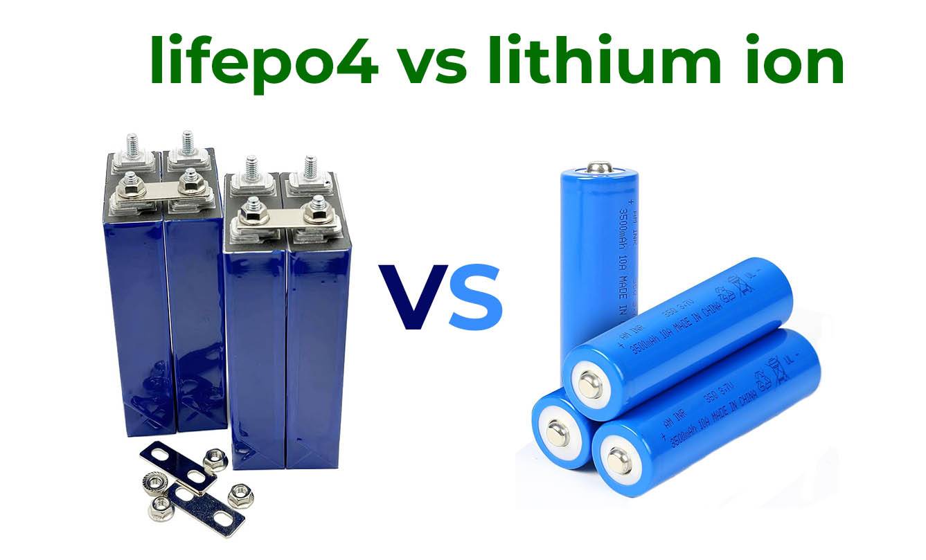
Main difference between LiFePO4 (Lithium Iron Phosphate) and Lithium-ion batteries
Keep in mind that the voltage values provided are rough estimates and can vary. LiFePO4 batteries are familiar for their relatively stable voltage profile. It’s voltage drop as the SOC decreases compared to other lithium-ion chemistries. Additionally, temperature can have a significant impact on battery voltage, so it’s important to consider the operating conditions.
| SOC (%) | Voltage per Cell (V) | Total Voltage (V) |
|---|---|---|
| 0 | < 2.80 | < 42.2 |
| 5% | ~2.80 | ~42.2 – 45.6 |
| 10% | ~3.00 | ~45.6 – 48.0 |
| 20% | ~3.20 | ~48.0 – 49.6 |
| 30% | ~3.30 | ~49.6 – 50.4 |
| 40% | ~3.35 | ~50.4 – 51.0 |
| 50% | ~3.40 | ~51.0 – 51.8 |
| 60% | ~3.45 | ~51.8 – 52.5 |
| 70% | ~3.50 | ~52.5 – 53.2 |
| 80% | ~3.55 | ~53.2 – 54.0 |
| 90% | ~3.60 | ~54.0 – 55.2 |
| 100% | ~3.65 | ~55.2 – 56.4 |
60V LiFePO4 Battery Voltage Chart:
A 60V LiFePO4 battery pack consist of 20 cells of 3.2v in series. Here is a approximate chart of 60V LiFePO4 battery voltage.
| SOC (%) | Voltage per Cell (V) | Total Voltage (V) |
|---|---|---|
| 0 | < 2.80 | < 48 |
| 5% | ~2.80 | ~49 |
| 10% | ~3.00 | ~49.9 |
| 20% | ~3.25 | ~51.7 |
| 30% | ~3.30 | ~53.8 |
| 40% | ~3.35 | ~55.8 |
| 50% | ~3.42 | ~57.6 |
| 60% | ~3.45 | ~59.5 |
| 70% | ~3.55 | ~61.4 |
| 80% | ~3.55 | ~63.4 |
| 90% | ~3.62 | ~65.3 |
| 100% | ~3.65 | ~67.3 |
72V LiFePO4 Battery Voltage Chart:
| SOC (%) | Voltage per Cell (V) | Total Voltage (V) |
|---|---|---|
| 0 | < 2.80 | < 60 |
| 5% | ~2.80 | ~61.2 |
| 10% | ~3.10 | ~62.4 |
| 20% | ~3.25 | ~64.8 |
| 30% | ~3.35 | ~67.2 |
| 40% | ~3.38 | ~69.2 |
| 50% | ~3.42 | ~72.0 |
| 60% | ~3.45 | ~74.4 |
| 70% | ~3.50 | ~76.8 |
| 80% | ~3.55 | ~79.2 |
| 90% | ~3.62 | ~81.6 |
| 100% | ~3.65 | ~84.0 |
Please keep in mind that the voltage values I provide are approximate value. It can vary depending on factors like battery capacity, charge/discharge rate, and battery age, quality, temperature and other factors.
To measure the voltage and current (amps) of a LiFePO4 battery, you’ll need appropriate measuring tools and follow safety precautions. Here’s how you can do it:
Measuring Voltage of LiFePO4 Battery:
- Safety First: Before proceeding, ensure you’re in a well-ventilated area and following proper safety guidelines for handling batteries.
- Select a Multimeter: You’ll need a digital multimeter capable of measuring DC voltage. Set the meter to the appropriate voltage range (typically 20V DC or higher).
- Connect the Leads: Connect the red (positive) probe of the multimeter to the positive terminal of the battery and the black (negative) probe to the negative terminal.
- Read the Voltage: The multimeter will display the voltage of the battery. Make sure to take note of the voltage reading.
Measuring Current (Amps) of LiFePO4 Battery:
- Safety Precautions: Be cautious when measuring current, as it requires breaking the circuit. Make sure you’re familiar with the circuit and any potential risks involved.
- Select a Multimeter: You’ll need a digital multimeter capable of measuring DC current. Make sure the multimeter’s current measurement range is suitable for the expected current draw (often the 10A range is used).
- Break the Circuit: To measure current, you’ll need to temporarily break the circuit that the battery is connected to. This can involve disconnecting a wire or using a current measurement tool like a clamp meter.
- Connect the Multimeter: If using a clamp meter, open the clamp and position it around one of the disconnected wires (either positive or negative). If using the multimeter’s leads, connect the circuit so the multimeter is in series (in line) with the current flow. Connect the red lead to the positive side and the black lead to the negative side.
- Read the Current: If using a clamp meter, the display will show the current directly. If using the multimeter’s leads, set the multimeter to the current measurement mode (often labeled as “A” or “mA” depending on the range). The multimeter will show the current in amps.
Remember to follow safety precautions, especially when dealing with current measurements. If you’re not comfortable with electrical work, it’s advisable to seek assistance from someone with experience or consult a professional.


Thanks for your marvelous posting! I truly enjoyed reading it,
you happen to be a great author.I will ensure that I bookmark your blog
and will often come back sometime soon. I
want to encourage that you continue your great writing, have
a nice evening!
Thank you very much.